Alu Circuit Diagram Using Multiplexer
Alu circuit diagram xor add Logic arithmetic multiplexer 16:1 mux : vlsi n eda
16:1 mux : VLSI n EDA
Dive into systems 3. arithmetic unit logic in an optimized 1-bit alu using 2:1 Mux multiplexer 8x1 diagram logic schematic using input table 16 vlsi truth 2x1 symbol muxes figure structure eda elcho
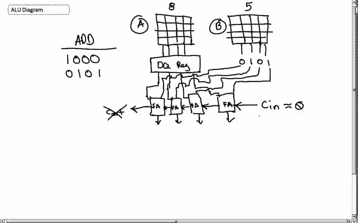
Alu circuit diagram (with add and xor)
Alu bit xor add performs code result operations condition zero operands function four figure two has cpu .
.


